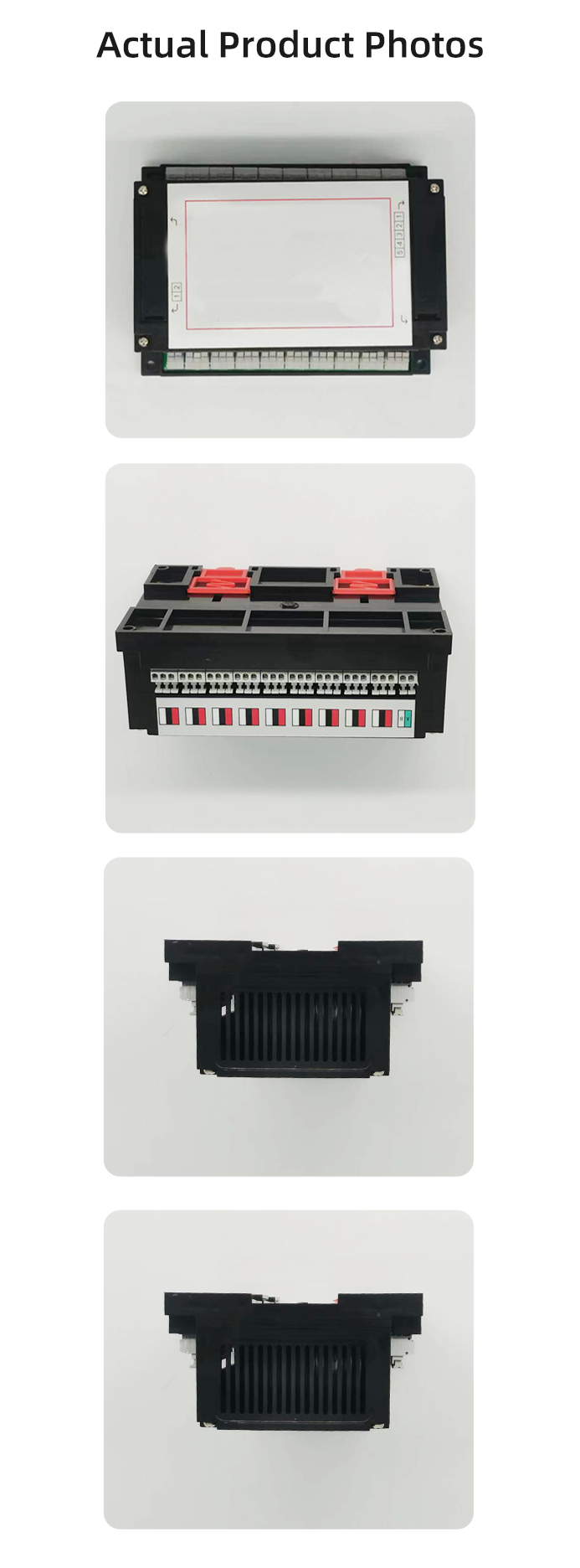
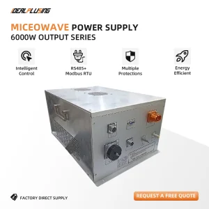
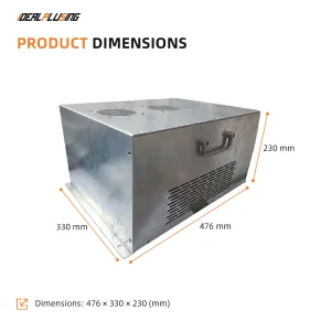
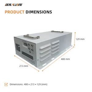
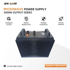
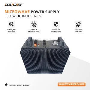
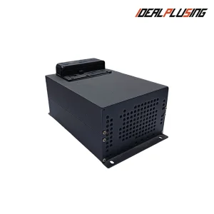
Product Description
Register Address Map (Hexadecimal)
| Register Address |
Description |
| Register Address 0x0000 | Magnetron 01 Output Power Code |
| Register Address 0x0001 | Magnetron 02 Output Power Code |
| Register Address 0x0002 | Magnetron 03 Output Power Code |
| Register Address 0x0003 | Magnetron 04 Output Power Code |
| Register Address 0x0004 | Magnetron 05 Output Power Code |
| Register Address 0x0005 | Magnetron 06 Output Power Code |
| Register Address 0x0006 | Magnetron 07 Output Power Code |
| Register Address 0x0007 | Magnetron 08 Output Power Code |
| Register Address 0x0008 | Magnetron 09 Output Power Code |
| Register Address 0x0009 | Magnetron 10 Output Power Code |
| Register Address 0x000A | Magnetron 11 Output Power Code |
| Register Address 0x000B | Magnetron 12 Output Power Code |
| Register Address 0x000C | Magnetron 13 Output Power Code |
| Register Address 0x000D | Magnetron 14 Output Power Code |
| Register Address 0x000E | Magnetron 15 Output Power Code |
| Register Address 0x000F | Magnetron 16 Output Power Code |
| Register Address 0x0010 | Magnetron 17 Output Power Code |
| Register Address 0x0011 | Magnetron 18 Output Power Code |
| Register Address 0x0012 | Channel 01 Operating Status Code |
| Register Address 0x0013 | Channel 02 Operating Status Code |
| Register Address 0x0014 | Channel 03 Operating Status Code |
| Register Address 0x0015 | Channel 04 Operating Status Code |
| Register Address 0x0016 | Channel 05 Operating Status Code |
| Register Address 0x0017 | Channel 06 Operating Status Code |
| Register Address 0x0018 | Channel 07 Operating Status Code |
| Register Address 0x0019 | Channel 08 Operating Status Code |
| Register Address 0x001A | Channel 09 Operating Status Code |
| Register Address 0x001B | Channel 10 Operating Status Code |
| Register Address 0x001C | Channel 11 Operating Status Code |
| Register Address 0x001D | Channel 12 Operating Status Code |
| Register Address 0x001E | Channel 13 Operating Status Code |
| Register Address 0x001F | Channel 14 Operating Status Code |
| Register Address 0x0020 | Channel 15 Operating Status Code |
| Register Address 0x0021 | Channel 16 Operating Status Code |
| Register Address 0x0022 | Channel 17 Operating Status Code |
| Register Address 0x0023 | Channel 18 Operating Status Code |
| Register Address 0x0024 | Channel 01 Operating Temperature |
| Register Address 0x0025 | Channel 02 Operating Temperature |
| Register Address 0x0026 | Channel 03 Operating Temperature |
| Register Address 0x0027 | Channel 04 Operating Temperature |
| Register Address 0x0028 | Channel 05 Operating Temperature |
| Register Address 0x0029 | Channel 06 Operating Temperature |
| Register Address 0x002A | Channel 07 Operating Temperature |
| Register Address 0x002B | Channel 08 Operating Temperature |
| Register Address 0x002C | Channel 09 Operating Temperature |
| Register Address 0x002D | Channel 10 Operating Temperature |
| Register Address 0x002E | Channel 11 Operating Temperature |
| Register Address 0x002F | Channel 12 Operating Temperature |
| Register Address 0x0030 | Channel 13 Operating Temperature |
| Register Address 0x0031 | Channel 14 Operating Temperature |
| Register Address 0x0032 | Channel 15 Operating Temperature |
| Register Address 0x0033 | Channel 16 Operating Temperature |
| Register Address 0x0034 | Channel 17 Operating Temperature |
| Register Address 0x0035 | Channel 18 Operating Temperature |
Note 1: The setting range for the magnetron output power codes at register addresses 0x0000-0x0011 is 25-132 (decimal).
Power Code Description
| Power Code |
Microwave Output Power |
Power Supply Input Power |
| 25 | 250W | 375W |
| 50 | 500W | 750W |
| 80 | 800W | 1200W |
| 100 | 1000W | 1500W |
| 132 | 1320W | 2000W |
Note 2: The temperature value output range for register addresses 0x0024-0x0035 is 70°C to 88°C. Over-temperature protection is triggered at 88°C, and the power supply module will shut down automatically.
Connection Status Code Description
(Extracted from the high 4 bits of the Operating Status Code)
| Status Code |
Connection Status Description |
| 0x00 | Power module communication line connection normal |
| 0xF0 | Power module communication line connection abnormal |
Operating Status Code Description
(Extracted from the low 4 bits of the Operating Status Code)
| Status Code |
Operating Status Description |
| 0x00 | Normal Operation |
| 0x01 | No Feedback Signal |
| 0x02 | Undervoltage Protection |
| 0x03 | Overvoltage Protection |
| 0x04 | Overcurrent Protection |
| 0x05 | Overtemperature Protection |
| 0x06 | Magnetron Fault |
| 0x07 | Surge Protection |
| 0x08 | High-Voltage Fault |
| 0x09 | Switching Tube Fault |
| 0x0A | No Power Signal |
| 0x0B | Vcc Protection |
Frame Data Description
| Function Code |
Description |
| 03 | Read Holding Registers |
| 06 | Preset Single Register |
| 16 | Preset Multiple Registers |
Read Holding Registers Master Frame Format (Function Code 03)
| Field Value |
Description |
| 0x01 | Slave Address 1 |
| 0x03 | Function Code 03 |
| 0x00 | High Byte of Starting Register Address |
| 0x12 | Low Byte of Starting Register Address (Start Address 0) |
| 0x00 | High Byte of Quantity of Registers |
| 0x02 | Low Byte of Quantity of Registers (Read 2 Data Points) |
| 0x64 | High Byte of CRC16 Checksum |
| 0x0E | Low Byte of CRC16 Checksum |
Function Description: Read 2 data points starting from register address 00 at slave address 01.
| Protocol Field |
Byte Value / Frame Data |
| Start Silent Interval | T1-T2-T3-T4 |
| Slave Address | 01 |
| Function Code | 03 |
| Register Address | 00 12 |
| Data Length | 00 02 |
| CRC16 Checksum | 64 0E |
| End Silent Interval | T1-T2-T3-T4 |
Read Holding Registers Slave Response Frame Format (Function Code 03)
| Field Value |
Description |
| 0x01 | Slave Address 1 |
| 0x03 | Function Code 03 |
| 0x04 | Number of Response Data Bytes (1 data point = 2 bytes high/low; 2×2=4 bytes) |
| 0x00 | High Byte of the 1st Data |
| 0xF1 | Low Byte of the 1st Data (Decimal value of this register: 100) |
| 0x00 | High Byte of the 2nd Data |
| 0xF1 | Low Byte of the 2nd Data (Decimal value of this register: 25) |
| 0x6A | High Byte of CRC16 Checksum |
| 0x44 | Low Byte of CRC16 Checksum |
Function Description: Feedback of 2 data points starting from register address 00 at slave address 01.
| Protocol Field |
Byte Value / Frame Data |
| Start Silent Interval | T1-T2-T3-T4 |
| Slave Address | 01 |
| Function Code | 03 |
| Data Length | 04 |
| Data | 00 F1 00 F1 |
| CRC16 Checksum | 6A 44 |
| End Silent Interval | T1-T2-T3-T4 |
Preset Single Register Master Frame Format (Function Code 06)
| Field Value |
Description |
| 0x01 | Slave Address 1 |
| 0x06 | Function Code 06 |
| 0x00 | High Byte of Register Address |
| 0x00 | Low Byte of Register Address |
| 0x00 | High Byte of Register Data |
| 0x64 | Low Byte of Register Data |
| 0x88 | High Byte of CRC16 Checksum |
| 0x21 | Low Byte of CRC16 Checksum |
Function Description: Set the data of register address 0x0F at slave address 01 to 0x64.
| Protocol Field |
Byte Value / Frame Data |
| Start Silent Interval | T1-T2-T3-T4 |
| Slave Address | 01 |
| Function Code | 06 |
| Register Address | 00 00 |
| Data | 00 64 |
| CRC16 Checksum | 88 21 |
| End Silent Interval | T1-T2-T3-T4 |
Preset Single Register Slave Response Frame Format (Function Code 06)
| Field Value |
Description |
| 0x01 | Slave Address 1 |
| 0x06 | Function Code 06 |
| 0x00 | High Byte of Register Address |
| 0x00 | Low Byte of Register Address |
| 0x00 | High Byte of Register Data |
| 0x64 | Low Byte of Register Data |
| 0x88 | High Byte of CRC16 Checksum |
| 0x21 | Low Byte of CRC16 Checksum |
Function Description: Feedback of the received data.
| Protocol Field |
Byte Value / Frame Data |
| Start Silent Interval | T1-T2-T3-T4 |
| Slave Address | 01 |
| Function Code | 06 |
| Register Address | 00 00 |
| Data | 00 64 |
| CRC16 Checksum | 88 21 |
| End Silent Interval | T1-T2-T3-T4 |
Preset Multiple Registers Master Frame Format (Function Code 16 / 0x10)
| Field Value |
Description |
| 0x01 | Slave Address 1 |
| 0x10 | Function Code 16 |
| 0x00 | High Byte of Starting Register Address |
| 0x00 | Low Byte of Starting Register Address |
| 0x00 | High Byte of Number of Registers |
| 0x03 | Low Byte of Number of Registers |
| 0x06 | Byte Count (6 bytes) |
| 0x00 | High Byte of Data 1 |
| 0x64 | Low Byte of Data 1 |
| 0x00 | High Byte of Data 2 |
| 0x64 | Low Byte of Data 2 |
| 0x00 | High Byte of Data 3 |
| 0x64 | Low Byte of Data 3 |
| 0xD7 | High Byte of CRC16 Checksum |
| 0x7C | Low Byte of CRC16 Checksum |
Function Description: Set the data of register addresses 00, 01, and 02 at slave address 01 to 0x64.
| Protocol Field |
Byte Value / Frame Data |
| Start Silent Interval | T1-T2-T3-T4 |
| Slave Address | 01 |
| Function Code | 10 (0x10) |
| Starting Register Address | 00 00 |
| Number of Registers | 00 03 |
| Byte Count | 06 |
| Data | 00 64 00 64 00 64 |
| CRC16 Checksum | D7 7C |
| End Silent Interval | T1-T2-T3-T4 |
Preset Multiple Registers Slave Response Frame Format (Function Code 16 / 0x10)
| Field Value |
Description |
| 0x01 | Slave Address 1 |
| 0x10 | Function Code 16 |
| 0x00 | High Byte of Starting Register Address |
| 0x00 | Low Byte of Starting Register Address |
| 0x00 | High Byte of Number of Registers |
| 0x03 | Low Byte of Number of Registers |
| 0x80 | High Byte of CRC16 Checksum |
| 0x08 | Low Byte of CRC16 Checksum |
Function Description: Feedback of the received data.
| Protocol Field |
Byte Value / Frame Data |
| Start Silent Interval | T1-T2-T3-T4 |
| Slave Address | 01 |
| Function Code | 10 (0x10) |
| Starting Register Address | 00 00 |
| Number of Registers | 00 03 |
| CRC16 Checksum | 80 08 |
| End Silent Interval | T1-T2-T3-T4 |
Applicable Scenarios
Due to the significant variations in operating environments and modes associated with industrial microwave equipment, the demands placed on the power supply itself are exceptionally high. Our microwave power supply products are currently deployed across a wide range of industries—including food, pharmaceuticals, timber, chemicals, tea, ceramics, UV-based exhaust gas treatment, and paper manufacturing—to facilitate essential processes such as drying, sterilization, chemical reactions, sintering, extraction, and heating.
Can I place a sample order?
Yes, sample orders are acceptable for quality evaluation and system testing during our initial cooperation.
What is the typical lead time for orders?
Most models are kept in stock. For sample orders, the standard lead time is 1-3 working days after payment is received.
Is there a Minimum Order Quantity (MOQ) limit?
We maintain a low MOQ policy. A single piece (1 unit) is available for sample evaluation and testing.
What shipping methods do you use and how long does delivery take?
We primarily ship via express carriers including DHL, UPS, FedEx, or TNT, which typically take 3-5 days to arrive. Air and ocean freight services are also optional for bulk shipments.
How is an order processed?
First, communicate your specific application requirements. Second, we provide a quotation based on those specifications. Third, the client confirms the samples and submits a deposit, after which we arrange production.
What is the warranty period for your products?
We offer a comprehensive 1-year product warranty coverage on all of our power supply units.